Seite 1 von 1

ETZ alternator rectifier and regulator

BeitragVerfasst: 28. September 2009 17:12
von SofCHJanek
Hello friends,
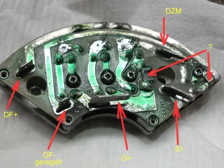
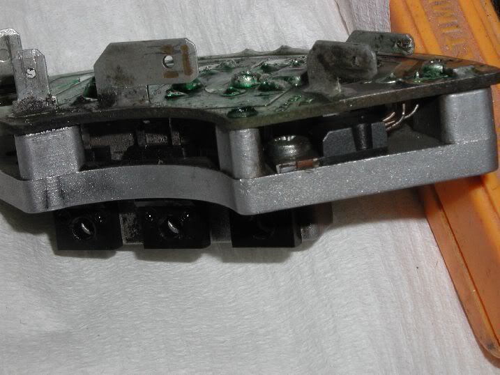
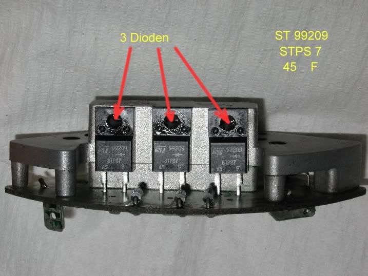
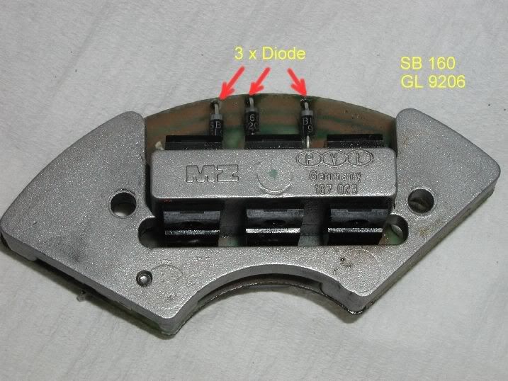
I have PVL rectifier-regulator and it was damaged -> http://www.mz-b.com/electric/mz/etz-pcb.jpg http://www.mz-b.com/electric/mz/etzlimav2.jpg
I wanna repair it but some elements was removed from board (pcb).
Maybe someone can make photos rectifier from each sides and write here names of all electronics elements.
Rectifier had 6 diodes - stps745F (45V 7,5A) and 3 diodes SB** propably 50V 2A and 2 unknow elements (removed).
Thanks, John

Re: ETZ alternator rectifier and regulator

BeitragVerfasst: 28. September 2009 21:34
von ANA-FÜ-250
Hallo Leute,
wollte den Kollegen hier nicht unbeantwortet durchreichen lassen.
Habe vom Problem selbst, keinen Schimmer Ahnung - deshalb sein Anliegen nochmal in DE.
Grüner Text stammt von mir.

Hallo Freunde,
ich habe einen PVL Gleichrichter/Regler und dieser wurde zerstört.
http://www.mz-b.com/electric/mz/etz-pcb.jpg
http://www.mz-b.com/electric/mz/etzlimav2.jpg
Ich möchte ihn nun gerne reparieren, aber einige Bauteile wurden von der Grundplatte entfernt. (Vermutlich von seiner Ersatzgrundplatte)
Vielleicht kann jemand von Euch ein paar Fotos von allen Seiten machen und nachträglich alle Bauteile (z.Bsp.: via "Paint") mit Namen/Bezeichnung beschriften.
Der Gleichrichter hatte sechs Dioden - stps745F (45V 7,5A) und drei Dioden SB** vermutlich 50V 2A (war evtl. unleserlich) sowie zwei unbekannte Bauteile (die, welche fehlen).
Danke, John


Hello John, this is only the translation to german, maybe there is somebody who can help you.
Regards René

Re: ETZ alternator rectifier and regulator

BeitragVerfasst: 28. September 2009 22:00
von Paule56
ANA-FÜ-250 hat geschrieben:Vielleicht kann jemand von Euch ein paar Fotos von allen Seiten machen


Drei sind nicht das Problem, aber die nützen bestimmt nicht viel ....
Die "each side" ist der springende Punkt, dazu muss ich nämlich die Lötstellen der Statorspulen trennen.
Aber ich hatte es eh schon in einem anderen fred versprochen.

-- Hinzugefügt: 29.09.2009 17:35:33 --

So, los gehts ... wenn auch noch immer problembehaftet

Die Anschlusskennzeichnung der Platine.

Bild

Hier der OPV, ist ein Dreibein und der Spalt so eng, dass die Beschriftung unlesbar ist.

Bild

Die lesbare Seite der Dioden

Bild

und die drei Hilfsdioden

Bild

@ Rene

erklär ihm bitte, dass ich nach hoffentlich positiv ausfallender Abklärung der thermischen Probleme weiter mache
Außer den 2 Briketts (mit dem Fragezeichen), einem Operationsverstärker und den insgesamt 9 Dioden ist da NIX weiter enthalten

Ich gehe damit jetzt bei Lothar, Günni und net-harry in dem Ursprungsthread betteln

Re: ETZ alternator rectifier and regulator

BeitragVerfasst: 29. September 2009 18:37
von SofCHJanek
Thanks for pictures, I saw it in other thread. Left element marked as "?" and element visibled on second picture (plastic package - this is regulator) are removed from my board.
I check some information on internet and probably STmicroelectronics made regulator, perhaps it has one of them symbols: L9480, L9444 - one chip, TO-220 package.
Thanks for help, John

Re: ETZ alternator rectifier and regulator

BeitragVerfasst: 29. September 2009 18:52
von ANA-FÜ-250
Hello John,
in the last answer from "Paule56" you can see the connection designations.
He means there is only a small gap between circuit board and base plate, so you can´t read the designations in this area.
Also he can´t make pictures from "each side", because for this the soldered points should be destroyed.
Currently he is clearing the termical problems with some specialists, after them he will give more informations.
In figure 1 you can find two parts with a question mark, he don´t know wat it is ( "Paule56" named it "coal briquet" :wink: ).
All in all there are 9 diodes, one operational amplifier and the two unkown parts.
So far so good - later more.

Regards,
René and "Paule56"